Background
Older diesel locomotives run control systems designed decades ago. They still work, but parts are hard to find and the documentation is partial. To modernize the locomotives, a new system must replace the old ones. To build it, you first need to understand exactly what the old systems do: which signals they receive, which commands they send, and in what order and timing.
The challenge
- No full documentation: the system's behavior has to be learned from the system itself, while it runs.
- No interference allowed: the connection must be listen-only, without affecting the locomotive.
- Different voltages: a locomotive has 5 V, 12 V, 24 V, 48 V and up to 72 V signals, sometimes in the same system.
- Many measurement points: many signals must be tracked in parallel, from different places in the locomotive.
What we built
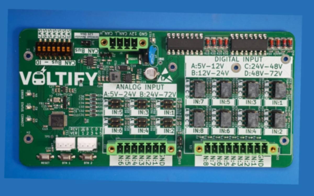
- 8 isolated digital inputs: full optical isolation, so the board listens without affecting anything. Each input's voltage range is selected by jumper: 5–12 V, 12–24 V, 24–48 V or 48–72 V.
- 6 analog inputs: voltage measurement in two ranges, 5–24 V and 24–72 V, selectable per input.
- Protection: a fuse on every digital input, and protection diodes on the analog inputs.
- CAN bus: several boards connect to the same line. Each board has an address set by a DIP switch, and a 120 Ω termination resistor enabled by jumper.
- Power over the CAN line: the same connector carries 12 V and communication, so there are fewer cables inside the locomotive.
- Firmware: sampling all channels, detecting changes and timing, and sending the data for collection and analysis.
- Operation: status LEDs (ERROR, STATUS, CONNECT), buttons, and programming and diagnostic connectors.
The result
A complete picture of how the old systems in the locomotive actually work: which signals, in what order and with what timing. This data is the basis for designing the new system that will replace them.